Go-Kart Gauge Cluster
2024
Category: Personal Project
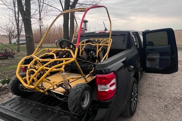
In March 2024, I decided to buy a used Go-Kart with the idea of using it as a fun project to fix up and drive around. Aside from some minor safety concerns, the main improvement I wanted to make was to add a speedometer as well as headlights, brake lights, and turn signals. The kart was very stripped down, so I would have to set up a a lot of this on my own.
Project Inspiration
After installing a new engine and belt-driven CVT, the need for some sort of speedometer became even more apparent. The increased acceleration made the kart feel faster, which made it even more difficult to gauge how fast I was going. But, because of the CVT, the rotation of the engine would not always be proportional to the rotation of the wheels. Because of this, I wanted to make a gauge cluster so that I could know the RPM of the engine as well as the speed of the kart, measured independently.

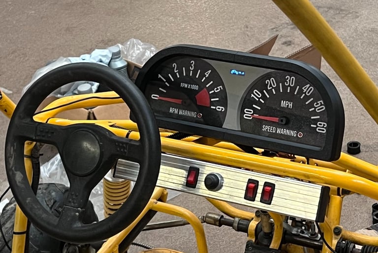
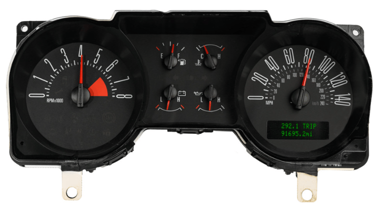
The original inspiration for the design came from the gauge cluster design for 2005-2009 Ford Mustangs. I didn't need the same gauges that the Mustang's cluster had in the middle, but I liked the idea of being able to live gear ratio of the CVT on a screen, calculated using the measurements I got of the engine and wheel RPM.
The Process
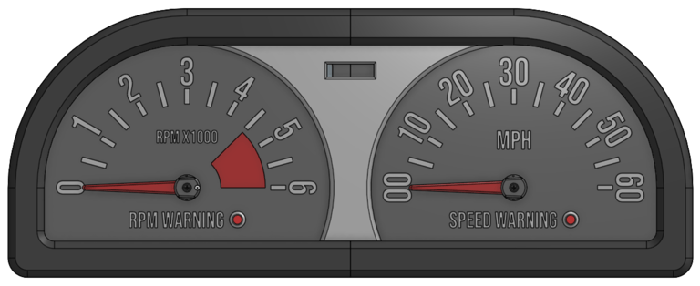
I designed the gauge faces around the idea of printing it with a 3D printer that could print in multiple colors (in this case, a Bambu Lab printer with an AMS unit). The gauge needles were powered with micro servos and the CVT's gear ratio would be displayed on a small OLED screen communicating with the microcontroller. Additionally, there were LED indicator lights that would be turned on in the unlikely event that I exceeded a specific engine RPM or kart speed, that way I would be alerted in my peripheral vision more clearly. To control the servos I mounted the front plate to a control box that would hold the microcontroller as well as the connectors for the sensors used to measure RPM. Additionally, I built in mounting points to allow for mounting of the components for turn signals and brake lights.
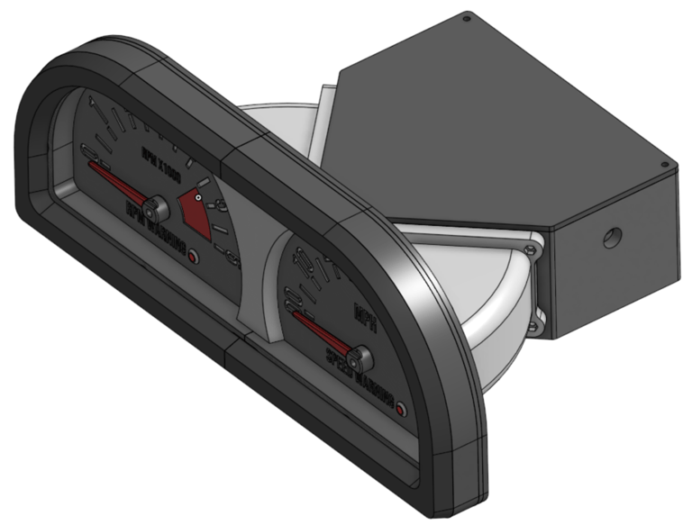
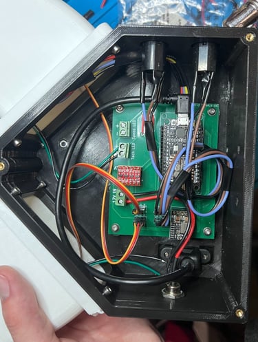
This project was my first introduction to PCB design, so I kept it fairly simple. The majority of components on the board were development boards, and there were no surface-mounted components. I used a magnet mounted to the rotating portion on each side of the CVT and used a magnetic presence sensor to measure each respective rotational speed. This was interpreted using a NodeMCU microcontroller that powered the gauge servos through a level shifter and the warning LEDs.

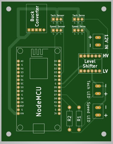
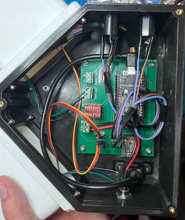
Inside the control box, the speed sensor terminals were connected to a panel-mounted socket for a 1/4" two-channel audio jack. This was to allow for easy connection as well as easy transmission of power and data to the three-wire sensor. For power, a 12V DC barrel jack panel-mount socket was used that fed into a buck converter to shift it down to the 5V used to run the microcontroller and sensors. 12V input was chosen because it could be attached to the same fuse box and 12V battery that the other accessories would be connected to, like the turn signals or brake light.
The gauge cluster worked out very well, not only in the aesthetics of the design but also the functionality it achieved. Although very rudimentary, I designed and ordered my first PCB and had some important learnings in the process. I found a real interest in schematic and PCB design, which led my interest in pursuing the future project with Glassboard Product Development, gb_macropad. Although there were unrelated bottlenecks on the Go-Kart and the gauge cluster has had limited field use, I am very pleased with how it turned out.
The Result